Why Correct Installation Is as Important as Correct Selection
Choosing the right safety valve is only half the job. Even a perfectly specified, certified device can fail to perform — or cause serious damage — if it is incorrectly installed. Studies and field reports consistently show that the majority of safety valve failures in service are not due to manufacturing defects, but to improper installation and commissioning practices.
This guide covers the fundamental rules for installing a safety valve correctly, the most frequent mistakes made on site, and the key requirements imposed by international standards including ISO 4126, API 520/521, and PED 2014/68/EU.
Before Installation: Pre-Commissioning Checks
Before fitting any safety valve, the following checks must be completed:
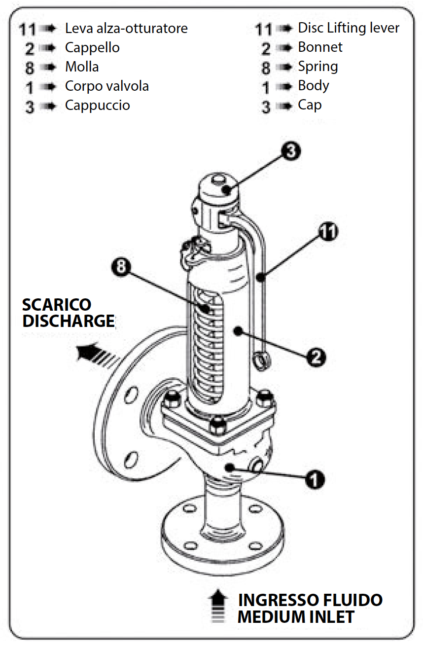
- Verify the valve data tag: Confirm that set pressure, capacity, fluid designation, and certification markings match the system requirements and the purchase specification.
- Inspect the valve externally: Check for any transport damage, corrosion, or contamination. Never install a valve with a broken seal wire — a broken seal means the valve must be returned for re-certification before use.
- Clean the upstream pipework: The system must be free of dirt, weld slag, scale, and any other debris before commissioning. Foreign material on the seat is one of the most common causes of valve leakage after installation.
- Check flange faces and gaskets: Flange faces must be clean, undamaged, and correctly rated. Always use new, appropriate gaskets — never reuse old ones.
Orientation: Vertical Is Non-Negotiable
Safety valves must be installed vertically upright, with the spindle in a vertical position. This is not a recommendation — it is a requirement of both ISO 4126 and API 520.
Installing a safety valve in a horizontal or inverted position has the following consequences:
- The spring force acts at an angle to the disc, causing uneven seat loading and leakage
- Drainage of condensate or process fluid from the body is prevented, accelerating corrosion and seat damage
- The valve may not open at the correct set pressure due to gravitational effects on the disc
- The installation may be non-compliant with applicable regulations, resulting in failed inspection
If the system layout makes vertical installation difficult, consult BESA’s technical team before proceeding. In some specific cases, manufacturers can provide guidance on alternative orientations — but these must always be explicitly approved.
Inlet Pipework: Keep It Short and Full Bore
The inlet connection between the protected equipment and the safety valve is a critical element that directly affects valve performance. The following rules must always be respected:
- Inlet pressure drop must not exceed 3% of set pressure (API 520 requirement). Excessive pressure drop causes the valve to close before the system pressure has fallen sufficiently, leading to rapid cycling and chatter.
- Inlet pipework must be as short and direct as possible. Never install the valve at the end of a long horizontal run that does not have normal process flow through it — this leads to the accumulation of condensate or debris that can interfere with valve operation.
- The inlet bore must be at least equal to the valve inlet connection size. Restrictions or reducers in the inlet line are not acceptable.
- No isolation valve between the protected equipment and the safety valve, unless a specific interlocked valve change-over system is provided and approved by the relevant authority.
Discharge Pipework: Protecting the Valve and the Plant
Discharge pipework is frequently underestimated. Poor discharge design is a leading cause of premature valve failure and plant incidents.
- Never attach discharge pipework directly to the valve outlet in a way that imposes weight or bending stress on the valve body. The discharge pipe must be independently supported.
- For steam and gas systems, discharge pipework should rise away from the valve to prevent condensate from accumulating at the valve outlet. Horizontal sections must slope downward at a minimum gradient of 1:100 away from the valve.
- For liquid systems, discharge pipework should fall away from the valve to ensure self-draining.
- Back pressure must be within the valve’s design limits. In a closed discharge system (manifold), the built-up back pressure at full flow must be verified against the valve type. Conventional valves are sensitive to back pressure; balanced-bellows designs are more tolerant.
- Drain points must be provided at all low points in the discharge system to prevent liquid accumulation.

Most Common Installation Mistakes
1. Installing the valve horizontally
As discussed, this invalidates the valve’s performance and may void the certification. Always verify orientation before commissioning.
2. Oversized or undersized inlet/outlet pipework
Restrictions in the inlet or excessive back pressure in the outlet are the most common causes of valve chatter, simmer, and premature seat wear in the field.
3. Using the valve as a pipe anchor
Safety valves are not structural elements. The weight of both inlet and outlet pipework must be carried by dedicated supports, not transferred to the valve body. Mechanical stress on the body causes distortion of the seat geometry and permanent leakage.
4. Commissioning without flushing the system
Starting up a system without first cleaning the pipework forces debris through the valve seat at high velocity. Even a single particle of weld slag can permanently damage a lapped metal seat. Always flush with the valve isolated or removed, then install the safety valve only on a clean, commissioned system.
5. Breaking the seal wire without authorisation
Safety valves are set, sealed, and certified at the factory or by an authorised body. Breaking the seal wire — even to check the spring adjustment — renders the valve non-compliant. Any adjustment must be performed by qualified personnel with a full re-certification process.
6. Ignoring the test gag after hydrostatic testing
If the system undergoes hydrostatic testing after the safety valve is installed, the valve must be either removed or fitted with a test gag (disc blocking device) to prevent the disc from lifting during the test. Failure to do so can permanently damage the seat surfaces.
Documentation and Traceability
Good installation practice includes maintaining a complete and up-to-date record of every safety valve in the plant. The valve register should include:
- Tag number and location
- Manufacturer, model, and serial number
- Set pressure, capacity, and fluid service
- Certification reference and expiry date
- Date of installation and commissioning
- History of tests, adjustments, and replacements
This documentation is not only good engineering practice — it is a mandatory requirement under PED 2014/68/EU and most national pressure equipment inspection regimes.
Conclusions
A safety valve that is correctly selected but incorrectly installed provides no reliable protection. The rules governing installation — orientation, inlet and outlet pipework design, support, cleanliness, and documentation — are well established in international standards and exist because field experience has demonstrated, repeatedly, what happens when they are ignored.
Taking installation seriously from the first day means fewer failures, longer valve service life, and — most importantly — a plant that is genuinely protected when it needs to be.
A correctly installed safety valve is an investment in years of reliable, trouble-free protection. A poorly installed one is a liability from day one.
Need Support for Your Installation?
BESA’s technical team provides full support from valve selection through to installation guidance and commissioning assistance. For questions about specific applications or to request a custom sizing, visit our online quotation form or download the BESA product catalogue.


